ESP32-POE-ISO
Select Product Variant
- ESP32-POE-ISO
- ESP32-POE-ISO-16MB
- ESP32-POE-ISO-16MB-IND
- ESP32-POE-ISO-EA
- ESP32-POE-ISO-EA-16MB
- ESP32-POE-ISO-EA-IND
- ESP32-POE-ISO-IND
- ESP32-POE-ISO-WROVER
- ESP32-POE-ISO-WROVER-EA
| Price | 26.95 EUR |
|---|---|
| 10 - 49 pcs | 24.26 EUR |
| 50 - 10000 pcs | 21.56 EUR |
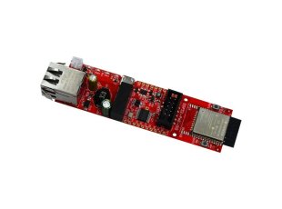
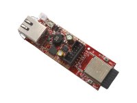
ESP32-PoE-ISO is an ESP32-powered WIFI/BLE/Ethernet development board with Power-Over-Ethernet feature. ESP32-POE-ISO has 3000VDC galvanic insulation from the Ethernet powering. It is the perfect addition to any project that requires connectivity.
The PoE is currently handled by TPS2375PW chip that is IEEE 802.3-compliant, including pre-standard (legacy) PoE support. The PoE powering requires at least 37V DC to operate successfully. The board takes power from the Ethernet cable and can be expanded with sensors and more. Perfect solution for Internet-of-Things projects.
ESP32-POE-ISO-EA has ESP32-WROOM-32UE module with U.FL connector and external antenna attached, which allow mounting in metal box. All "-EA" variants have antenna included!
ESP32-POE-ISO and ESP32-POE-ISO-EA operate in the commercial temperature range 0-70C
ESP32-POE-ISO-IND and ESP32-POE-ISO-EA-IND are functionally identical, but use components rated for industrial temperature operation -40+85C
ESP32-POE-ISO-16MB and ESP32-POE-ISO-EA-16MB are with ESP32-WROOM with 16MB Flash.
ESP32-POE-ISO-WROVER comes with ESP32-WROVER-E with 4MB flash and 8MB PSRAM, while ESP32-POE-WROVER-EA uses ESP32-WROVER-IE (again with 4MB flash and 8MB PSRAM). Notice that WROVER module requires two extra pins for the PSRAM - some software changes related to Ethernet and I2C might be required.
FEATURES
- ESP32 module with WiFi and bluetooth (exact module depends on variant)
- High reliable industrial grade -40+85C available (-IND)
- CE-RED and LVD certification
- Original design by OLIMEX Ltd
- Low power design - 200uA consumption in deep sleep
- Ethernet 100Mb interface with IEEE 802.3af PoE support
- 3000VDC galvanic insulation between the PoE Ethernet part and board's power supply circuit
- Micro USB connector for ESP32 programming
- MicroSD card working in 1 bit mode (3 more GPIOs)
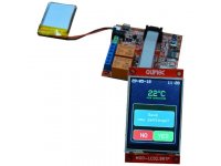
- LiPo battery charger with LiPo battery connector
- Battery level monitor pin on ADC
- External power supply detection pin on ADC
- DC-DC 2W 5V/400mA
- UEXT connector
- User button
- Reset button
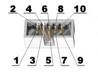
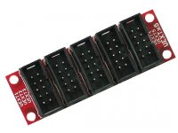
- Two extension connectors, 0.1" step spaced at 1"
- PCB dimensions: (98 x 28)mm ~ (3.8 x 1)"
DOCUMENTS
SOFTWARE
Works with any software that has ESP32 chip support. There is configuraiton for the board in most popular tools like the ESP32 package for Arduino, esphome, Tasmota, etc.Demo software
- All Arduino IDE and ESP-IDF demos at our GitHub pages
- ESPHome yaml configs
- PlatformIO json configs
- ESPectre motion detector
USB drivers
Related Products - People who bought this product also bought
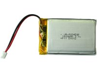
Rechargable LI-PO battery 3.7V 1400mAh with JST connector
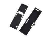
Plastic box for ESP32-POE-ISO
- BOX-ESP32-POE-ISO
- BOX-ESP32-POE-ISO-EA-F
- BOX-ESP32-POE-ISO-F
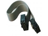
UEXT 10-pin female-female replacement cable
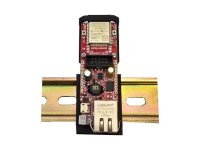
Aluminum clip for DIN rail with Plastic seat for ESP32-POE ESP32-POE2 and ESP32-POE-ISO boards
- DIN-CLIP-ESP32-POE
- DIN-CLIP-ESP32-POE-ISO
- DIN-CLIP-ESP32-POE2
ESP32-POE IoT development board with 100Mb Ethernet, Power over Ethernet, WiFi, BLE, programmer
- ESP32-POE
- ESP32-POE-16MB
- ESP32-POE-EA
- ESP32-POE-EA-16MB
- ESP32-POE-EA-IND
- ESP32-POE-IND
- ESP32-POE-WROVER
- ESP32-POE-WROVER-EA
USB 2.0 Type A to MICRO with 1.0 / 1.8 m length
- USB-CABLE-A-MICRO-1.8M
- USB-CABLE-A-MICRO-1M