MOD-WIFI-ESP8266
Select Product Variant
- MOD-WIFI-ESP8266
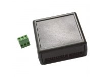
- MOD-WIFI-ESP8266-BOXED
| Price | 3.45 EUR |
|---|---|
| 10 - 49 pcs | 3.28 EUR |
| 50 - 10000 pcs | 3.11 EUR |
MOD-WIFI-ESP8266 is OSHW certified Open Source Hardware with UID BG000013
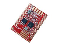
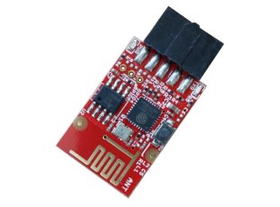
MOD-WIFI-ESP8266 is UEXT expansion module with the famous ESP8266 UART to WIFI IC. With this module you can add WIFI capablities to other Olimex development boards with UEXT connector. The board comes with 2MB of SPI flash memory.
The BOXED version has neat protective cover with cutout for the boot button.
The idea of MOD-WIFI-ESP8266 is to use it as an easy hardware expansion of existing Olimex boards. That is why it has UEXT connector. You plug it in another board with UEXT connector and the hardware connections are complete. It is visible in the schematics that MOD-WIFI-ESP8266 uses only first 4 pins of the UEXT – #1 (3.3 Vcc), #2 (GND), #3 (RXD), #4 (TXD). This means only a data UART interface is available. The rest of the pins of the chip are not routed for easier access - if you need more signals consider MOD-WIFI-ESP8266-DEV or ESP8266-EVB. In order to program the board you can use the button.
MOD-WIFI-ESP8266 is recommended for people that already have some experience with ESP8266. Consider ESP8266-EVB if you are a complete beginner. If you want to add WIFI capabilites to own board, consider MOD-WIFI-ESP8266-DEV.
FEATURES
- Main chip: EPS8266EX
- 2MB (16Mb) SPI flash memory
- Button to swap between FLASH and UART mode
- SMT jumpers for different boot modes (FLASH, UART, SDO)
- UEXT connector
- Power LED
- User-programmable LED
- PCB antenna
- Pads for a U.FL antenna connector (if you want to use external antenna)
- OSHW desgn
- Dimensions: (1.38 x 0.69)" ~ (3.50 x 1.75)cm
DOCUMENTS
- Boot modes reference (FLASH, UART, SDIO)
- ESP8266EX datasheet
- How to update firmware
- More ESP8266EX-related documents are available here: official espressif web-site and here: official espressif forum
- MOD-WIFI-ESP8266 European Declaration of Conformity
- MOD-WIFI-ESP8266 UKCA Declaration of Conformity
HARDWARE
FAQ
-
How do I send AT commands to the board?
-
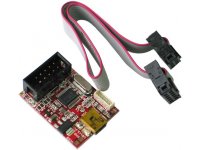
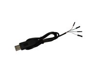
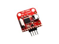
You need to establish UART connection to the board (using RX, TX, GND). The best approach is to use a USB to serial cable with 3.3V TTL converter and 3.3V power supply. The board's jumpers has to be in default FLASH mode. You would either need to use a cable that can power targets, or split the GND line. The reason is that the power supply needs a GND line and the cable needs a GND line but the board has only a single GND on the connector (UEXT pin #2). You can use MOD-USB-RS232 for easy connection to a personal computer (you would need to change the jumpers of MOD-USB-RS232 to be able to power the MOD-WIFI-ESP8266 and to communicate with it; once this is done it becomes a plug-and-play setup)
-
How do I put the board in UART mode (so I can change the firmware or upload program via Arduino IDE)?
-
Press and hold the button and then apply power supply; release the button. Alternatively, set the jumpers to UART mode, and after the upload is done revert them back to the original FLASH mode.
-
I want to send basic AT commands to the board but I receive no response. The strange thing is that I receive "ready" when I power the module. What is the problem?
-
All AT commands must end with carriage return and line feed - "/r/n". Your terminal software might have such a new line option - transmiting CR+LF at the end of each command. If it doesn't - either use another terminal software or try to send the commands with "CTRL"+"J" keyboard combination, instead of "ENTER".
-
I send basic AT commands to the board but I receive only "ERROR" response. What is the problem?
-
The commands are case sensitive. Make sure you are using capital letters.
-
Newly purchased boards can't be programmed via Arduino IDE. What is the difference compared to previous revisions?
-
The SPI memory had to be changed due to unvailability of the original one. New memory requires different flash mode, make sure to select QOUT instead of QIO (as it was before). Refer to the latest schematic.
Related Products - People who bought this product also bought
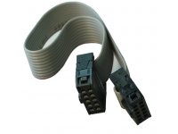
UEXT 10-pin female-female replacement cable
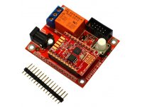
ESP8266-EVB is Evaluation board for ESP8266 with relay, button, UEXT, all GPIOs available on 0.1" header
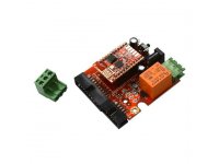
ESP8266-EVB is Evaluation board for ESP8266 with relay, button, UEXT, all GPIOs available on boxed connector