ESP32-POE-ISO  

ESP32-POE-ISO - Open Source Hardware Board
ESP32-POE-ISO - Open Source Hardware Board ESP32-POE-ISO - Open Source Hardware Board ESP32-POE-ISO - Open Source Hardware Board
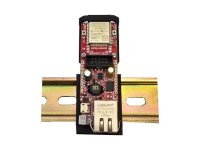
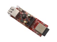
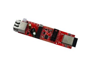
ESP32-POE-ISO IoT development board with 100Mb Ethernet, Power over Ethernet, WiFi, BLE, programmer

Select Product Variant

  • ESP32-POE-ISO
  • ESP32-POE-ISO-16MB
  • ESP32-POE-ISO-16MB-IND
  • ESP32-POE-ISO-EA
  • ESP32-POE-ISO-EA-16MB
  • ESP32-POE-ISO-EA-IND
  • ESP32-POE-ISO-IND
  • ESP32-POE-ISO-WROVER
  • ESP32-POE-ISO-WROVER-EA
Price25.95 EUR
10 - 49 pcs23.36 EUR
50 - 10000 pcs20.76 EUR
In Stock
ESP32-POE-ISO is OSHW certified Open Source Hardware with UID BG000021

ESP32-PoE-ISO is an ESP32-powered WIFI/BLE/Ethernet development board with Power-Over-Ethernet feature. ESP32-POE-ISO has 3000VDC galvanic insulation from the Ethernet powering. It is the perfect addition to any project that requires connectivity.

The PoE is currently handled by TPS2375PW chip that is IEEE 802.3-compliant, including pre-standard (legacy) PoE support. The PoE powering requires at least 37V DC to operate successfully. The board takes power from the Ethernet cable and can be expanded with sensors and more. Perfect solution for Internet-of-Things projects.

ESP32-POE-ISO-EA has ESP32-WROOM-32UE module with U.FL connector and external antenna attached, which allow mounting in metal box. All "-EA" variants have antenna included!

ESP32-POE-ISO and ESP32-POE-ISO-EA operate in the commercial temperature range 0-70C

ESP32-POE-ISO-IND and ESP32-POE-ISO-EA-IND are functionally identical, but use components rated for industrial temperature operation -40+85C

ESP32-POE-ISO-16MB and ESP32-POE-ISO-EA-16MB are with ESP32-WROOM with 16MB Flash.

ESP32-POE-ISO-WROVER comes with ESP32-WROVER-E with 4MB flash and 8MB PSRAM, while ESP32-POE-WROVER-EA uses ESP32-WROVER-IE (again with 4MB flash and 8MB PSRAM). Notice that WROVER module requires two extra pins for the PSRAM - some software changes related to Ethernet and I2C might be required.

FEATURES

  • ESP32 module with WiFi and bluetooth (exact module depends on variant)
  • High reliable industrial grade -40+85C available (-IND)
  • CE-RED and LVD certification
  • Original design by OLIMEX Ltd
  • Low power design - 200uA consumption in deep sleep
  • Ethernet 100Mb interface with IEEE 802.3 PoE support
  • 3000VDC galvanic insulation between the PoE Ethernet part and board's power supply circuit
  • Micro USB connector for ESP32 programming
  • MicroSD card working in 1 bit mode (3 more GPIOs)
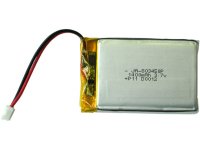
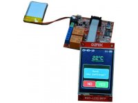
  • LiPo battery charger with LiPo battery connector
  • Battery level monitor pin on ADC
  • External power supply detection pin on ADC
  • DC-DC 2W 5V/400mA
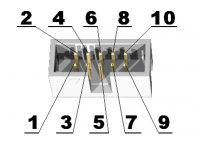
  • UEXT connector
  • User button
  • Reset button
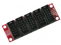
  • Two extension connectors, 0.1" step spaced at 1"
  • PCB dimensions: (98 x 28)mm ~ (3.8 x 1)"

FAQ

  • ESP32-PoE-ISO doesn't work well with bauds over 115200. What to do?
  • Some older drivers might have wrong timings, causing worse throughput. Download and install the latest drivers for CH340. If you are using Linux make sure to try with these drivers: high-speed driver for Linux
  • Is it safe to have USB powering and PoE powering connected and enabled at the same time?
  • Yes, when using ESP32-POE-ISO it is safe to have them both enabled.
  • I got WROVER board and my Ethernet code and my I2C code doesn't appear to work. My device is broken, how do I return it?
  • Your ESP32-POE-ISO-WROVER is not broken and we test each device with Ethernet, chances of broken device are very low. However, there is hardware difference in the pinout between boards with WROOM and WROVER modules - the WROVER module requires two extra pins for the PSRAM memory. One of the pins affects the Ethernet, the other - the I2C.

    When WROVER module is used (instead of the default WROOM) then GPIO16 and GPIO17 are unavailable (both are used for the PSRAM inside the module). In that case we have set GPIO33 to go on UEXT1 pin #5 (instead of GPIO16). Also the clock for the Ethernet is now GPIO0 (instead of GPIO17). Modify your software for these differences.
  • Where are I2C, UART, SPI pins exposed?
  • The ESP32 chip has very advanced multiplexing and you can define any free GPIO pin for I2C, UART, SPI operation as long as you are within the maximum supported (some penalties to SPI's maximum freqncy apply, when not using the dedicated pins). Notice that some ESP32 pins can only be inputs. Defining pins is for another job is purely software effort.
  • I provide 24V to the input of ESP32-PoE-ISO's Ethernet but it doesn't seem powered. What is the problem?
  • TPS2375PW (Si3402) would NOT work with 24V DC. The recommended voltage is 48V DC and the minimum is around 37V DC. For more info refer to TPS2375PW's (Si3402-B's) datasheet.
  • I power the board from the Ethernet connector. What current do I have availabe for additional circuits?
  • The isolated DCDC that we use provides up to 2W, this means 400mA @ 5V, 100mA are reserved for the battery charge (available if no battery is connected) and 100mA are provided for ESP32, which leaves up to 200mA @ 5V for your additional circuit.
  • I power the board from the battery connector. The LEDs remain off. Is it borken?
  • Probably not. This is a low-power design. The LEDs would not turn on when operating on battery to save power. You need other ways to determine if it works or not. For example, something over the serial lines or over the Ethernet (with no PoE enabled else it would get powered from there).
  • R41 gets very hot when board is powered from Power-Over-Ethernet! What is this component? Is it safe? Can I remove it?
  • This resistor is required by the IEEE standards. It is used for MPS (maintain power signature). Search online "maintain power signature poe" to get the general idea. It consumes around 0.5W, when the board is powered from Power-Over-Ethernet (notice R41 consumes 0 when the board is powered from other sources).

    We didn't ensure MPS in the first hardware revisions of the board (e.g. had no resistor R41 in place), but this caused availability problems when using some power saving modes - the board consumed less wattage than PoE equipment can detect, which led to PoE equipment shutting the board off.

    If you have soldering experience and the resistor bothers you, you might try desoldering it and see if that effects your setup negatively. Notice that we don't recommend doing so.