ESP8266-EVB-BAT-BOX
| Price | 11.95 EUR |
|---|
ESP8266-EVB-BAT is OSHW certified Open Source Hardware with UID BG000016
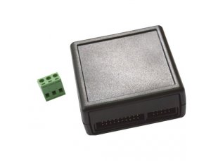
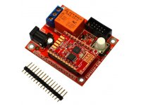
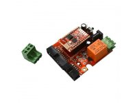
ESP8266-EVB-BAT is an evaluation board for the highly-integrated WIFI SoC ESP8266EX. The board comes with a custom-cut box HAMMOND box. The board can be powered by Li-Po battery and comes with a battery charger. It is recommended for beginners with ESP8266.
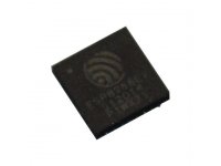
ESP8266EX is very highly integrated SoC which includes Tensilica's L106 32-bit core processor; SRAM; power management unit; RF front end. ESP8266EX has a number of interfaces - I2C, SPI, SDIO and also a number of free GPIO pins. The chip allows the implementation of a WIFI TCP-IP stack with just few extra components beside the ESP8266EX. It's a very popular IC that attracted a lot of attention upon its launch.
This board is suitable for resarch and development of espressif's ESP8266EX chip. The module be used for home automation, smart plugs and lights, mesh networks, industrial wireless control, baby monitors, IP cameras, sensor networks, wearable wlectronics, etc.
FEATURES
Board features:
- Includes ESP8266-EVB-BAT
- Protective HAMMOND box 1593KBK
- All connectors accessible when the box is closed
- Box dimensions: (2.60 x 2.65)" ~ (66 x 67)mm
ESP8266-EVB-BAT features:
- Relay 220VAC/10A with two-part Wago connector and status LED
- Big button for easier access to UART mode
- LiPo battery connector with built-in LiPo charger and status LEDs
- Step up converter
- Power jack for +5V external power supply
- UEXT connector
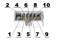
- 20-pin connector CON1 with ESP8266's signals
- PCB dimensions: (2.0 x 2.2)" ~ (51 x 57)mm
DOCUMENTS
- How to program the board with Arduino IDE
- How to update firmware
- ESP8266EX datasheet
- More ESP8266EX-related documents are available here: official espressif web-site and here: official espressif forum
- ESP8266-EVB-BAT-BOX European Declaration of Conformity
- ESP8266-EVB-BAT-BOX UKCA Declaration of Conformity
SOFTWARE
- Olimex Github ESP8266 resources
- MOD-TC-MK2 and ESP8266 boards - Arduino IDE library and examples
- ESP8266 vendor repository
FAQ
-
How do I send AT commands to the board?
-
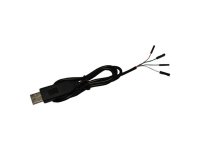
You need to establish UART connection to the board's UEXT (using RX, TX, GND). The best approach is to use a USB to serial cable with 3.3V TTL converter and a terminal program. Then power the board in standard "boot from FLASH mode" (no button pressed during power-up).
-
I want to send basic AT commands to the board but I receive no response. The strange thing is that I receive "ready" when I power the module. What is the problem?
-
All AT commands must end with carriage return and line feed - "/r/n". Your terminal software might have such a new line option - transmiting CR+LF at the end of each command. If it doesn't - either use another terminal software or try to send the commands with "CTRL"+"J" keyboard combination, instead of "ENTER".
-
I send basic AT commands to the board but I receive only "ERROR" response. What is the problem?
-
The commands are case sensitive. Make sure you are using capital letters.
-
Newly purchased boards can't be programmed via Arduino IDE. What is the difference compared to previous revisions?
-
The SPI memory had to be changed due to unvailability of the original one. New memory requires different flash mode, make sure to select QOUT instead of QIO (as it was before). Refer to the latest schematic.
Related Products - People who bought this product also bought
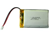
Rechargable LI-PO battery 3.7V 1400mAh with JST connector
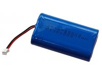
Rechargable LI-PO battery 3.7V 4400mAh with JST connector
ESP8266-EVB is Evaluation board for ESP8266 with relay, button, UEXT, all GPIOs available on 0.1" header
ESP8266-EVB is Evaluation board for ESP8266 with relay, button, UEXT, all GPIOs available on boxed connector
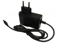
Power supply adapter 5V/1A 40Hz-50Hz/100V-240V(EUROPEAN STYLE PLUG!)