≡
ESP32-CAM
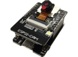
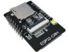
ESP32-CAM low cost WiFi CAM development board with OV2640 2 Mega Pixel Camera module 4MB PSRAM and 8MB FLASH
Select Product Variant
- ESP32-CAM
- ESP32-CAM-2MB
- ESP32-CAM-4MB
| Price | 10.95 EUR |
|---|
ESP32-CAM is a low cost development board with WiFi camera. It allows creating IP camera projects for video streaming with different resolutions. ESP32-CAM-MB allows to program the main board via micro USB.
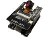
ESP32-CAM has build in PCB antenna but the ESP32 module also has U.FL connector - this allows the connecttion of an external antenna.
ESP32-CAM and ESP32-CAM-2MB now are obsolete.
ESP32-CAM-4MB is with 4MB PSRAM and 8MB FLASH which allow more AI apps to run.
ESP32-CAM has build in PCB antenna but the ESP32 module also has U.FL connector - this allows the connecttion of an external antenna.
ESP32-CAM and ESP32-CAM-2MB now are obsolete.
ESP32-CAM-4MB is with 4MB PSRAM and 8MB FLASH which allow more AI apps to run.
FEATURES
- ESP32-CAM-4MB + OV2640 2M pixel camera with connector
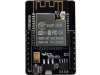
- ESP32-CAM-4MB contains ESP-32S SoC with Wi-Fi and BLE connectivity
- ESP32-CAM-4MB has micro SD card connector
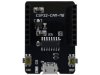
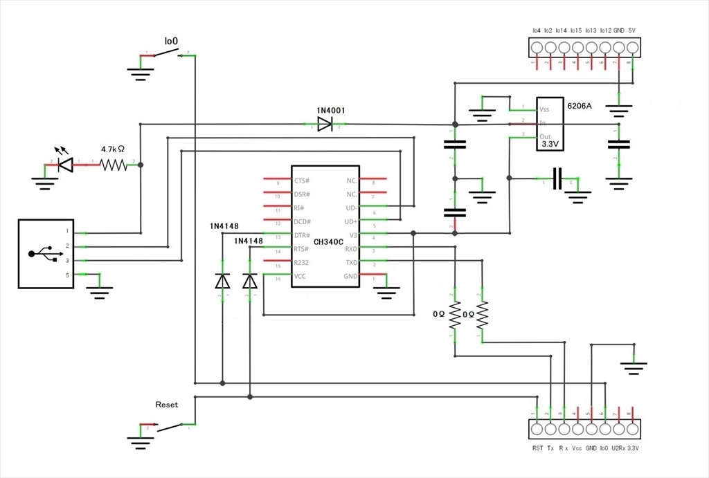
- ESP32-CAM-MB provides micro USB - serial communicationl (CH340) and reset and boot buttons
- The ESP32 module contains u.FL connector for possible external antenna atachement
DOCUMENTS
SOFTWARE
FAQ
- How do I connect the camera? It doesn't want to go into the connector.
- You need to carefully pull the front darker part of the connector up, towards you. It will release the lock and allow to place the connector, then you push back the lock mechanism to keep it in place.
- I don't get image from the camera. I can only see light source if placed next to the camera. What migth be wrong?
- Maybe you haven't removed the plastic cap over the camera's lens. Pull the cap carefully while holding the base.
- How to switch between internal PCB antenna and external antenna?
- You need to change the position of the resistor located to the right next the u.FL connector. This requires unsoldering and soldering it again in opposite position. By default its right side goes near the PCB antenna, it needs to go to the position near the u.FL connector. The left side of the resistor keeps the same pad.
Related Products - People who bought this product also bought
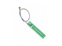
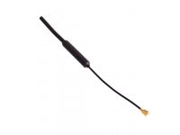
ANTENNA 2.4GHz for WIFI BLUETOOTH WITH UFL CONNECTOR
1.00 EUR
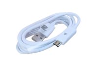
USB 2.0 Type A to MICRO with 1.0 / 1.8 m length
- USB-CABLE-A-MICRO-1.8M
- USB-CABLE-A-MICRO-1M
3.00 EUR

