MOD-RS485
| Price | 2.95 EUR |
|---|---|
| 10 - 49 pcs | 2.80 EUR |
| 50 - 10000 pcs | 2.66 EUR |
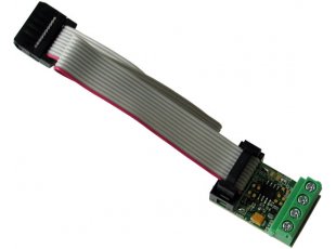
Using this module you can easily connect our development boards (that feature UEXT connector) to industrial networks with a RS485 interface, metering instruments etc.
MOD-RS485 is a small module board created with the help of an ADM3483ARZ - a low power, differential line transceiver, designed to operate using a single 3.3 V power supply, for half-duplex communication. This module can be used to convert RS232 signals into RS485 signals. The board comes with a 10 pin cable for the UEXT, via which it can be connected to each of our development boards with a UEXT on it. This module is an excellent choice for conveying information over long distances, allowing an error-free data transmission at data rates up to 250 kbps.
The module uses UART interface and two control pins to establish connection to the host board (all required signals available at the UEXT header).
FEATURES
- Half-duplex transceiver ADM3483ARZ from Analog Devices
- UEXT connector
- RS485 connector
- FR-4, 1.5 mm, soldermask, component print
- Dimensions: 30.99x20.32mm (1.22 x 0.80")
DOCUMENTS
FAQ
- Hello, I can't establish proper connection to the board. What do I do wrong?
- MOD-RS485 uses data UART signals (pins #3 and #4 of the UEXT) and two control signals (by default pins 9 and 10).
You can't skip using the control singals that define whether you transmit or receive data (completly disconnecting the jumpers SCL/SCK and #SS/SDA is also a bad idea). They are used like a normal digital I/O.
For example, If you are going for half-duplex communication: to send data set both SCK (pin #9) and #SS (pin #10) to high level. Send your data and check if it was successfully sent. Then to receive data set both SCK and #SS to low level.
Despite what it might look like - MOD-RS485 does NOT use I2C interface. MOD-RS485 may use the pins that are marked as SCL and SDA (if you change the default positons of jumpers SCL/SCK and #SS/SDA). However, not to establsish I2C interace, but as digital IOs. These two pins are ADM3483ARZ’s signals called "DE" and "/RE" – driver output enable and receiver enable. You would need to set the levels at those pins if you want to avoid seeing your own transmission.
Check the wiring of ADM3483ARZ in the MOD-RS485 schematic and read the description of the signals in the data sheet of ADM3483ARZ for more information.
Related Products - People who bought this product also bought
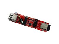
ESP32-POE-ISO IoT development board with 100Mb Ethernet, Power over Ethernet, WiFi, BLE, programmer
- ESP32-POE-ISO
- ESP32-POE-ISO-16MB
- ESP32-POE-ISO-16MB-IND
- ESP32-POE-ISO-EA
- ESP32-POE-ISO-EA-16MB
- ESP32-POE-ISO-EA-IND
- ESP32-POE-ISO-IND
- ESP32-POE-ISO-WROVER
- ESP32-POE-ISO-WROVER-EA
Galvanically isolated RS485/RS422 converter module with UEXT