Difference between revisions of "A20-OLinuXino-MICRO"
(→How to generate Arch Linux image?) |
(→How To?) |
||
| Line 306: | Line 306: | ||
== How To? == | == How To? == | ||
| + | |||
Revision as of 06:22, 13 January 2014

A20-OLinuXino-MICRO features:
- A20 Cortex-A7 dual-core ARM Cortex-A7 CPU and dual-core Mali 400 GPU
- 1GB DDR3 RAM memory
- 4GB NAND FLASH memory
- SATA connector with 5V SATA power jack
- HDMI FullHD 1080p
- 2x USB Low-Full-High-Speed hosts with power control and current limiter
- USB-OTG with power control and current limiter
- VGA output on 6-pin 1.25mm (0.05") step connector
- 100MBit native Ethernet
- LiPo Battery connector with battery-charging capabilities
- Audio headphones output
- Microphone input on connector
- 2x UEXT connectors
- LCD connector compatible with with 4.3", 7.0", 10.1" LCD modules from Olimex
- 160 GPIOs on three GPIO connectors
- MicroSD card connector
- SD/MMC card connector
- DEBUG-UART connector for console debug with USB-SERIAL-CABLE-F
- status LED
- Battery charge status LED
- Power LED
- 2KB EEPROM for MAC address storage and more
- 10 BUTTONS with ANDROID functionality + RESET button
- 4 mount holes
- 6-16V input power supply, noise immune design
- PCB dimensions: 142 x 82 mm
Contents
- 1 Official Images from OLIMEX
- 2 Documents
- 3 Hardware
- 4 Software
- 5 How To?
- 5.1 How to generate boot-able SD-card Debian Linux image for A20-OLinuXino?
- 5.2 How to download new Android image to the NAND memory of my A20 board?
- 5.3 How do I write the official Android image to a micro SD card for my A20 board?
- 5.4 How do I write the Linux image to a micro SD card to use with my A20 board?
- 5.5 How to change HDMI, VGA and LCD resolutions?
- 5.6 How to generate Arch Linux image?
- 5.7 How to detect and enable the Ethernet controller (if it is disabled by default)?
- 5.8 How to install Android on SD-card?
- 5.9 How to access UART, I2C, GPIOs under Android?
- 5.10 How to control PWM under Linux?
Official Images from OLIMEX
Note only microSD card will boot, SD-MMC card on the back will not boot as not part of boot sequence (reffer to A20 datasheet).
Linux
ULTIMATE A20 Debian 4GB SD-card image release-5 with:
- Linux Kernel 3.4.67+
- XFCE4 desktop environment
- Mplayer CLI
- GCC 4.6
- 4.3"(480x272), 7"(800x480), 10" (1024x600) and 15.6" (1366x768) LCD and touchscreen support
- GPIO
- I2C
- USB WIFI RTL8188CU, Ethernet AX88772B
- Audio (MIC and Headphones)
- dpkg
- git
- i2c-tools
- perl
- xorg
- Python 2.7
- OpenCV
- Scratch
- vlc
- USB-ETHERNET-AX88772B
- MOD-WIFI-RTL8188
- A13-LCD 4.3″TS 4.3″ LCD with backlight and touchscreen 480×272 pixels
- A13-LCD7″TS 7″ LCD with backlight and touchscreen 800×480 pixels
- A10-LCD10″TS 10.1″ LCD with backlight and touchscreen 1024×600 pixels
- HDMI
- Micro SD card
- SD/MMC card
- OTG USB
- HIGH SPEED HOST1 USB
- HIGH SPEED HOST2 USB
- ETHERNET 100MBIT
- SATA
- Audio IN
- Audio OUT
- I2C2(400KHz)
- I2C1(200KHz)
- Default Login: root/olimex
Tested board peripherials with this image:
- GPIO - located at /sys/class/gpio
- LCD - supported are A13-LCD4.3TS, A13-LCD7TS, A13-LCD10TS
- Touch screen - you need calibrate LCD before using touch screen. Type: ts_calibrate and then test it with ts_test
- SATA - works including power on/off control
- HDMI - the default HDMI resolution is 720p60(1280x720-60 Hz)
- ASIX 8877 USB-LAN - USB-ETHERNET-AX88772B
- WEB camera A4TECH
- TL-WN721(TP-LINK USB wireless)
- RTL8188CU - MOD-WIFI-RTL8188
- USB_OTG - works as OTG device and Low/Full/High USB host
- USB_HOST_up - works as Low/Full/High USB host
- USB_HOST_down - works as Low/Full/High USB host
- mico_SD_card - allow Linux boot
- secondary SD-MMC card - with card present detector
- ETHERNET - 100Mb
- Headphone OUT - audio output
- MIC IN - microphone input
- I2C2(100KHz) - /dev/i2c-2
- I2C1(100KHz) - /dev/i2c-1
- UART6 - /dev/ttyS1
- UART7 - /dev/ttyS2
Note: the A20-Debian-SD card which we have in our web store contains the same image on 4GB Class10 fast micro SDcard, if you want to use this image please use card of Class10 speed or the performance of Linux will be very slow.
Note: in the previous Debian releases the Ethernet was auto-detected and initialized during boot BUT this was causing big delays in the start-up of the board if you didn't want to use Ethernet or if there wasn't Ethernet cable connected.
You can enable it by following these two steps:
1. To check under what name the LAN is associated write "ifconfig –a"
2. If, for example, it is under eth0 name, then write: "dhclient eth0"
This should enable the Ethernet and then SSH would also be available.
Android
Android 4.2.2 NAND image made with A20-SDK2.0 for A13-LCD7"TS and A13-LCD10"TS
Android 4.2.2 SD-card image made with A20-SDK2.0 for A13-LCD7"TS and A13-LCD10"TS
The image is with these features:
- Android 4.2.2
- NAND image i.e. will work only on A20-OLinuXino-MICRO-4GB
- Supports 7" LCD 800x480 pixels and 10" LCD 1024x600 pixels
- HDMI support (720p default)
- both LCD and HDMI work together
- Touchscreen supported
- GPIO support
- Native Ethernet 100Mbit
- USB-Ethernet ASIX 88772
- USB-WIFI RTL8188
- USB-OTG support USB device and USB host with Low/Full/High speed
- USB-HOST-top Low/Full/High speed
- USB-HOST-bottom Low/Full/High speed
- micro SD card
- Audio OUT
- Audio In
- I2C1
- I2C2
- UART6
- UART7
- Buttons
What left unsupported:
- SATA
- SD-MMC card on bottom
A20-SDK2.0
A20-SDK 2.0 for building Android images
A20-SDK-V1.2
A20-SDK 1.2 for building Android images
Documents
A20-OLinuXino Board User Manual
A20 Brief
A20 Datasheet
A20 User Manual
Hardware
Power supply and consumption
A20-OLinuXino can be powered from three sources:
- +6-16VDC voltage applied PWR jack
- +3.7V from LiPo re-chargable battery connected to LiPo board connector
- +5V applied to USB-OTG connector
Power consumption is as follows:
- LiPo 3.7V power battery: 0.17-0.25A depend on processor load
- +6VDC input power: 0.18-0.33A depend on processor load
- +16VDC input power: 0.11-0.17A depend on processor load
LiPo battery allow backup power supply when main power is interrupted. A20-OLinuXino have power managment IC which charge the battery when main power is present, when power is interrupted the LiPo battery automatically provide backup power supply. Step-up converter prvide 5V for the USB peripherials too. For LiPo batteries we recommend these:
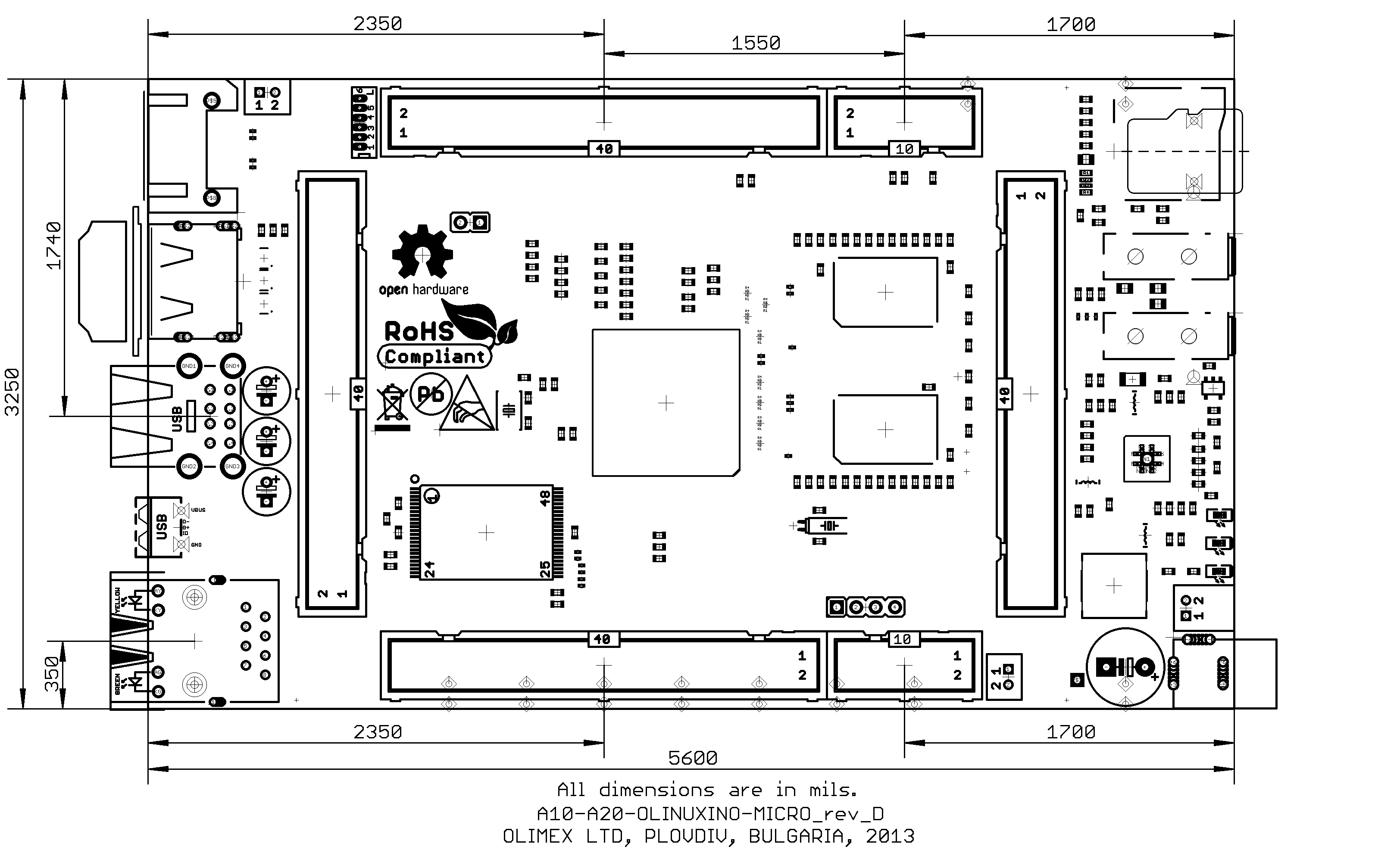
Board dimensions
A20-OLinuXino-MICRO and A20-OLinuXino-MICRO-4GB basic dimensions in mils: image in PNG format
CAD files
A20-OLinuXino is Open Source Hardware, CAD files are available at GitHub
The CAD product used to design OLinuXino is Eagle and you can download evaluation free version from their web.
Board Layout


Software
Python
pyA20 is Python library for access to A20-OLinuXino-MICRO GPIOs, I2C, SPI
Use:
   #!/usr/bin/env python

   import A20_GPIO as GPIO

   #init module
   GPIO.init()

   #configure module
   GPIO.setcfg(GPIO.PIN#, GPIO.OUTPUT)
   GPIO.setcfg(GPIO.PIN#, GPIO.INPUT)

   #read the current GPIO configuration
   config = GPIO.getcfg(GPIO.PIN#)

   #set GPIO high
   GPIO.output(GPIO.PIN#, GPIO.HIGH)

   #set GPIO low
   GPIO.output(GPIO.PIN#, GPIO.LOW)

   #read input
   state = GPIO.input(GPIO.PIN#)

   #cleanup
   GPIO.cleanup()
GPIO under Linux
In order to use A20 GPIO's first you have to export them. For example:
root@A20:~# for i in `seq 1 1 230`; do echo $i > /sys/class/gpio/export; done
list of all available GPIO
   root@A20:~# ls /sys/class/gpio/
   export       gpio21_pc3/  gpio33_pb8/  gpio45_ph27/ gpio57_ph17/ gpio69_pg5/
   gpio10_pe9/  gpio22_pc7/  gpio34_pb10/ gpio46_ph0/  gpio58_ph18/ gpio6_pe5/
   gpio11_pe10/ gpio23_pc16/ gpio35_pb11/ gpio47_ph2/  gpio59_ph19/ gpio70_pg6/
   gpio12_pe11/ gpio24_pc17/ gpio36_pb12/ gpio48_ph7/  gpio5_pe4/   gpio71_pg7/
   gpio13_pi14/ gpio25_pc18/ gpio37_pb13/ gpio49_ph9/  gpio60_ph20/ gpio72_pg8/
   gpio14_pi15/ gpio26_pc23/ gpio38_pb14/ gpio4_pe3/   gpio61_ph21/ gpio73_pg9/
   gpio15_pi0/  gpio27_pc24/ gpio39_pb15/ gpio50_ph10/ gpio62_ph22/ gpio74_pg10/
   gpio16_pi1/  gpio28_pb3/  gpio3_pe2/   gpio51_ph11/ gpio63_ph23/ gpio75_pg11/
   gpio17_pi2/  gpio29_pb4/  gpio40_pb16/ gpio52_ph12/ gpio64_pg0/  gpio7_pe6/
   gpio18_pi3/  gpio2_pe1/   gpio41_pb17/ gpio53_ph13/ gpio65_pg1/  gpio8_pe7/
   gpio19_pi10/ gpio30_pb5/  gpio42_ph24/ gpio54_ph14/ gpio66_pg2/  gpio9_pe8/
   gpio1_pe0/   gpio31_pb6/  gpio43_ph25/ gpio55_ph15/ gpio67_pg3/  gpiochip1/
   gpio20_pi11/ gpio32_pb7/  gpio44_ph26/ gpio56_ph16/ gpio68_pg4/  unexport
Example how to toggle onboard LED. The LED is connected to PH2.
root@A20:~# cd /sys/class/gpio/gpio47_ph2
make PH2 output
root@A20:/sys/class/gpio/gpio47_ph2# echo out > direction
write 1 to PH2 - LED is ON
root@A20:/sys/class/gpio/gpio47_ph2# echo 1 > value
write 0 to PH2 - LED is OFF
root@A20:/sys/class/gpio/gpio47_ph2# echo 0 > value
Add Voice to your OLinuXino project
Installation of Festival on OLinuXino
How To?
How to generate boot-able SD-card Debian Linux image for A20-OLinuXino?
Follow our blog post with step by step instructions Note that Linux-Sunxi Kernel is a work-in-progress, this means you can try the current stage/sunxi-3.4 branch but if something is broken and doesn't work just revert to the git tags we give in the blog and they should work for sure
Sunxi u-boot loader The linux-sunxi git page contains a lot of sources for all Olimex Allwinner boards.
How to download new Android image to the NAND memory of my A20 board?
To repair the image on the NAND re-upload it following these steps:
- 1. Install and run PhoenixSuit (can be found here: download from google drive).
- 2. Go to firmware tab of the program and point to a valid Android image (the latest official one may also be downloaded above).
- 3. Disconnect the power supply and USB cable from the A20 board.
- 4. Press and hold RECOVERY button, apply power supply (6-16)V, release RECOVERY button.
- 5. Connect USB cable to the mini USB connector.
- 6. You will be asked for drivers for the bootloader. Navigate to the folder where you extracted the PhoenixSuit and install the drivers from the respective executables (or manually point the installer to the drivers folder in the PhoenixSuit installation path).
- 7. PhoenixSuit will detect the board and would ask for the method of writing the image. Choose method of writing the image and confirm your wish to write the image.
- 8. Wait till upgrade succeeds
Note that it is not recommended to have your mini USB connected to an external USB hub. This might cause delays and might distort the signal levels. Always test with the USB connected straight to the USB ports of your computer.
How do I write the official Android image to a micro SD card for my A20 board?
There are two Android images available for an SD card. One for 7″ LCD and one for 10″ LCD A20-OLinuXino-MICRO#Android. Note that Android display configuration settings are edited in the script.bin file (it has to be converter to fex and edited according to the fex guide at linux sunxi's article; then converted back to script.bin and written in the image). To write the images on the SD card you will need PhoenixSuit and to follow these steps:
• Install and run PhoenixSuit
• Go to the firmware tab of the program and point to a valid Android image (note that the images on Gdrive are compressed and you have to extract them to .img files to be able write them with PhoenixSuit)
• Disconnect the power supply and USB cable from the A20 board. Put an SD card in micro SD holder. We recommend 4GB class 10 card.
• Press and hold RECOVERY button, apply power supply (6-16)V, release RECOVERY button.
• Connect USB cable to the mini USB connector.
• You will be asked for drivers for the boot-loader. Navigate to the folder where you extracted the PhoenixSuit and install the drivers from the respective executables (or manually point the installer to the drivers folder in the PhoenixSuit installation path).
• PhoenixSuit will detect the board and would ask for the method of writing the image. Choose method of writing the image and confirm your wish to write the image.
• Wait till upgrade succeeds
Note that it is not recommended to have your mini USB connected to an external USB hub. This might cause delays and might distort the signal levels. Always test with the USB connected straight to the USB ports of your computer.
Important: When Android runs for very first time it takes several minutes to initialize all files and buffers please do not cut the power supply during this process! Also when fresh image is installed fast boot may be disabled, which means that when you apply power supply after few seconds Android will go in sleep mode and you have to press POWER button to start it, you can change to fast boot when you power off there is dialog box asking you if you want next boot to be fast boot, you have to check this box before you power off. Also note that you must do touch screen calibration when you run Android for very first time which might require a mouse.
How do I write the Linux image to a micro SD card to use with my A20 board?
To write a Linux image to an SD card under Windows we use Win32 Disk Imager):
- Download Win32 Disk Imager Win32 Disk Imager
- Insert card
- Start program
- Select file
- Click "write"
To write a Linux image to an SD card under Linux:
For instance you have an image with the file name of "debian_2g.img". It would be downloaded to the SD card connected to a Linux machine using one of the following commands:
- # dd bs=4M oflag=sync if=debian_2g.img of=/dev/sdX
or
- # cp debian_2g.img /dev/sdX
where X is the uSD card.
How to change HDMI, VGA and LCD resolutions?
The default SD card setup is made with settings for HDMI 720p/60Hz. If you want to change to some other LCD, VGA or HDMI resolution then you have to start change_display.sh script file in /root directory.
Type:
# ./change_display.sh
and choose the resolution and the interface(LCD, HDMI or VGA). Note that the selection of a specific resolution is done by navigating with the arrow keys and pressing "space" button. Make sure the asterisk marks your selection properly.
The supported resolutions are:
For LCD:
- 1. 4.3" (480x272)
- 2. 7" (800x480)
- 3. 10" (1024x600)
- 4. 15.6" (1366x768)
Important: initially the boards are calibrated for a specific display. If you re-write the image (no matter whether the SD card or the NAND memory) you would need to use a mouse to calibrate the display initially. It might be impossible to calibrate it via touching the display.
For HDMI:
- 0. 480i
- 1. 576i
- 2. 480p
- 3. 576p
- 4. 720p50
- 5. 720p60
- 6. 1080i50
- 7. 1080i60
- 8. 1080p24
- 9. 1080p50
- 10. 1080p60
For VGA: (note that the VGA signals are routed to custom 6 pin connector and you need from adapter to standard VGA connector)
- 0. 1680x1050
- 1. 1440x900
- 2. 1360x768
- 3. 1280x1024
- 4. 1024x768
- 5. 800x600
- 6. 640x480
- 7. 1920x1080
- 8. 1280x720
How to generate Arch Linux image?
Step by step instructions how to build Arch Linux image
How to detect and enable the Ethernet controller (if it is disabled by default)?
Note: in the previous Debian releases the Ethernet was auto-detected and initialized during boot BUT this was causing big delays in the start-up of the board if you didn't want to use Ethernet or if there wasn't Ethernet cable connected.
You can enable it by following these two steps:
1. To check under what name the LAN is associated write "ifconfig –a"
2. If, for example, it is under eth0 name, then write: "dhclient eth0"
This should enable the Ethernet and then SSH would also be available.
How to install Android on SD-card?
How to access UART, I2C, GPIOs under Android?
Use our Open Source OLinuXino A20-TOOLS
How to control PWM under Linux?
There is an article here: how to add pwm
- Content is available under GNU Free Documentation License 1.3 or later unless otherwise noted.

