Difference between revisions of "A13-SOM"
(→Linux) |
(→How to change HDMI, VGA and LCD resolutions?) |
||
| Line 251: | Line 251: | ||
where X is the uSD card. | where X is the uSD card. | ||
| − | ===How to change HDMI, VGA and LCD resolutions? | + | ===General=== |
| + | |||
| + | '''How to change HDMI, VGA and LCD resolutions under Debian?''' | ||
The default SD card setup is made with settings for HDMI 720p/60Hz. If you want to change to some other LCD, VGA or HDMI resolution then you have to start change_display.sh script file in /root directory. | The default SD card setup is made with settings for HDMI 720p/60Hz. If you want to change to some other LCD, VGA or HDMI resolution then you have to start change_display.sh script file in /root directory. | ||
Revision as of 23:21, 16 October 2014


A13-SOM-XXX features:
- A13 Cortex-A8 CPU and Mali 400 GPU
- 256 or 512MB DDR3 RAM memory
- Power supply managment
- 1x LCD connector
- 3x GPIO connectors
- MicroSD card connector
- DEBUG-UART connector for console debug with USB-SERIAL-CABLE-F
- status LED
- Power LED
- RESET button
- 3.3V input power supply
- PCB dimensions: 61 x 33 mm
Contents
- 1 Official Images from OLIMEX
- 2 Documents
- 3 Hardware
- 4 Software
- 5 How To?
- 5.1 How to correctly power off OLinuXino running from NAND Flash
- 5.2 How to generate boot-able SD-card Debian Linux image for A13-SOM?
- 5.3 How do I write the Linux image to a micro SD card to use with my A13-SOM board?
- 5.4 General
- 5.5 How to control PWM under Linux?
- 5.6 How to edit board configurations and definitions in the official Debian Linux?
- 5.7 How to properly calibrate a display under Debian
- 5.8 How to add STK1160 video capture driver support in Kernel 3.4
Official Images from OLIMEX
Linux
Torrent of Debian release 1: A13-SOM-256 Debian Linux with kernel 3.4.90+
Direct download location of Debian release 1: A13-SOM-256 Debian 4GB SD-card image release-1 with hardware accelerated video and more
Torrent of Debian release 1: A13-SOM-512 Debian Linux with kernel 3.4.90+
Direct download location of debian release 1: A13-SOM-512 Debian 4GB SD-card image release-1 with hardware accelerated video and more
The image features:
- Linux Kernel 3.4.90+
- LXDE desktop environment
- Mplayer CLI
- GCC 4.6
- 4.3"(480x272), 7"(800x480), 10" (1024x600) and 15.6" (1366x768) LCD and touchscreen support
- GPIO
- I2C
- USB WIFI RTL8188CU, Ethernet AX88772B
- dpkg
- git
- i2c-tools
- perl
- xorg
- Python 2.7
- USB-ETHERNET-AX88772B
- MOD-WIFI-RTL8188
- A13-LCD 4.3″TS 4.3″ LCD with backlight and touchscreen 480×272 pixels
- A13-LCD7″TS 7″ LCD with backlight and touchscreen 800×480 pixels
- A10-LCD10″TS 10.1″ LCD with backlight and touchscreen 1024×600 pixels
- Micro SD card
- OTG USB
- HIGH SPEED HOST1 USB
- I2C2(100KHz)
- I2C1(100KHz)
- Default Login: root/olimex
Tested board peripherals with this image:
- GPIO - located at /sys/class/gpio
- LCD - supported are A13-LCD4.3TS, A13-LCD7TS, A13-LCD10TS
- Touch screen - you need calibrate LCD before using touch screen. Type: ts_calibrate and then test it with ts_test
- ASIX 8877 USB-LAN - USB-ETHERNET-AX88772B
- RTL8188CU - MOD-WIFI-RTL8188
- USB_OTG - works as OTG device and Low/Full/High USB host
- USB_HOST - works as Low/Full/High USB host
- mico_SD_card - allow Linux boot
- I2C2(100KHz) - /dev/i2c-2
- I2C1(100KHz) - /dev/i2c-1
Note: the A13-SOM-Debian-SD card which we have in our web store contains the same image on 4GB Class10 fast micro SDcard, if you want to use this image please use card of Class10 speed or the performance of Linux will be very slow.
Note: in the previous Debian releases the Ethernet was auto-detected and initialized during boot BUT this was causing big delays in the start-up of the board if you didn't want to use Ethernet or if there wasn't Ethernet cable connected.
You can enable it by following these two steps:
1. To check under what name the LAN is associated write "ifconfig –a"
2. If, for example, it is under eth0 name, then write: "dhclient eth0"
This should enable the Ethernet and then SSH would also be available.
Android
Note that the Android is suitable only for the A13-SOM-512 version of the board (the 256 version of the board is not equipped with enough RAM to run Android smoothly). To upload the Android to the NAND you would also need A13-SOM-WIFI-4GB (to extend the board with NAND flash memory).
Torrent of Android 4.2.2 release 1 for NAND memory: A13-SOM-512 Android for NAND
Direct download of Android 4.2.2 release 1 NAND memory: A13-SOM-512 Android for NAND
The image is with these features:
- Android 4.2.2
- NAND image i.e. will work only on [A13-SOM-512+A13-SOM-WIFI-4GB]
- Supports 7" LCD 800x480 pixels
- Touchscreen supported
- GPIO support
- USB-Ethernet ASIX 88772
- USB-WIFI RTL8188
- USB-OTG support USB device and USB host with Low/Full/High speed
- USB-HOST-top Low/Full/High speed
- micro SD card
- I2C1
- I2C2
- Buttons
Documents
A13 Datasheet
A13 User Manual
Hardware
Power supply and consumption
If used as a stand-alone board A13-SOM can be powered from:
- +3.3V power source, applied to GPIO-1 connector
Power consumption is as follows:
Additonally, if used together with A13-SOM-WIFI the whole setup can be powered from:
- +5V via miniUSB cable, applied to USB_OTG connector
- +5V power source, applied to the +5V pin near the red PWR_LED
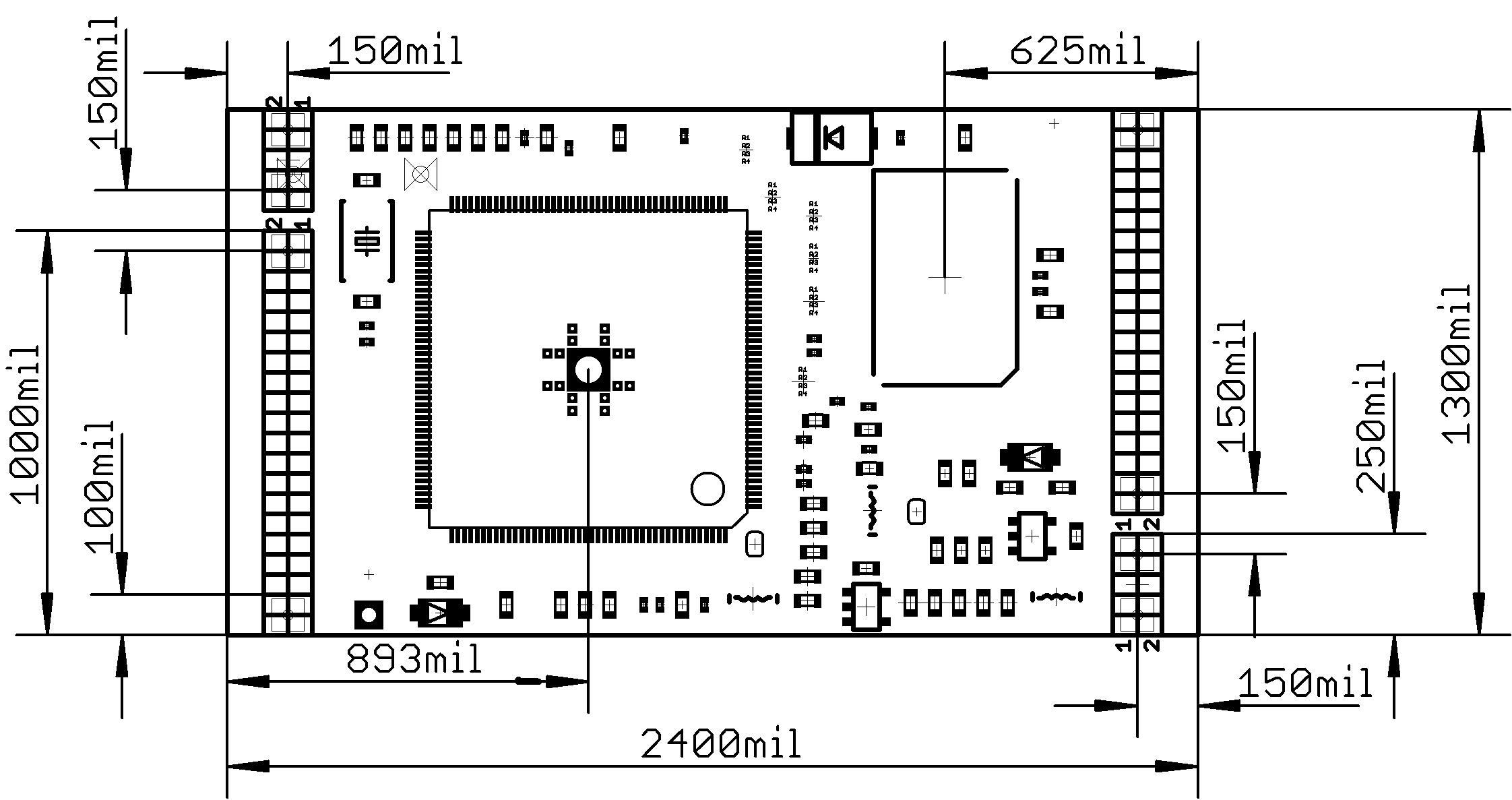
Board dimensions
A13-SOM-XXX basic dimensions might be seen in the picture here: A13-SOM board dimensions
Schematic
A13-SOM-256/512 schemaitc is available at GitHub
A13-SOM-WIFI schematic and CAD files are at GitHub
The CAD product used to design A13-SOM-WIFI is Eagle and you can download evaluation free version from their web.
Board Layout

Software
Linux Commands
Linux-Commands Brief Linux Command reference
Python
The Debian Linux Python package for A13-SOM is called pyA13SOM. It is installed in the default Debian image. More information and examples on how it can be used might be found here:
Link to pyA13SOM package at python.org
GPIO under Debian Linux
The GPIOs are defined in the script.bin of the Debian distribution. If you edit the script.bin you can change the names of the GPIOs. You can also remove the definitions for certain pins or add additional ones that we might have missed.
Inside the Debian Linux the GPIOs are located in /sys/class/gpio directory. Before using a GPIO you would need to export it.
There is an easy way to export all GPIOs:
 mount -t debugfs none /sys/kernel/debug
 for i in `seq 1 1 230`; do echo $i > /sys/class/gpio/export; done
To list all available GPIOs write:
cat /sys/kernel/debug/gpio
This would return:
 gpio-1   (sysfs               ) in  hi
 gpio-2   (sysfs               ) in  hi
 gpio-3   (sysfs               ) out hi
 gpio-4   (sysfs               ) in  lo
 gpio-5   (sysfs               ) in  lo
 gpio-6   (sysfs               ) in  lo
 gpio-7   (sysfs               ) in  lo
 gpio-8   (sysfs               ) in  lo
 gpio-9   (sysfs               ) in  lo
 gpio-10  (sysfs               ) in  hi
 gpio-11  (sysfs               ) in  lo
 gpio-12  (sysfs               ) in  lo
 gpio-13  (sysfs               ) in  hi
 gpio-14  (sysfs               ) in  lo
The rest of the GPIOs have to be defined in the fex. Refer to this wiki article: how to edit board configurations and definitions
An example for a single port add is below (PB03):
root@A13:~# echo 1 > /sys/class/gpio/export
to make PB03 output
root@A13:~# echo out > /sys/class/gpio/gpio1_pb3/direction
to make PB03 high level(3.3V)
root@A13:~# echo 1 > /sys/class/gpio/gpio1_pb3/value
to make PB03 low level(0V)
root@A13:~# echo 0 > /sys/class/gpio/gpio1_pb3/value
note that:
There might be multiplexing on some of the pins especially if you are using a shield! Consider that when picking a GPIO. Refer to the schematics of the board and the shield for clearer view of the possible multiplexing locations.
How To?
How to correctly power off OLinuXino running from NAND Flash
In this Blog post we explain what are the problems. This is common problem for all computers running OS. Here you can read more about MLC NAND Flash and Linux file system.
How to generate boot-able SD-card Debian Linux image for A13-SOM?
The building instructions might be found in this document: Google drive mirror
Official Wordpress post on Debian image release: Wordpress post
How do I write the Linux image to a micro SD card to use with my A13-SOM board?
To write a Linux image to an SD card under Windows we use Win32 Disk Imager):
- Download Win32 Disk Imager Win32 Disk Imager
- Insert card
- Start program
- Select file
- Click "write"
To write a Linux image to an SD card under Linux:
For instance you have an image with the file name of "debian_2g.img". It would be downloaded to the SD card connected to a Linux machine using one of the following commands:
- # dd bs=4M oflag=sync if=debian_2g.img of=/dev/sdX
or
- # cp debian_2g.img /dev/sdX
where X is the uSD card.
General
How to change HDMI, VGA and LCD resolutions under Debian?
The default SD card setup is made with settings for HDMI 720p/60Hz. If you want to change to some other LCD, VGA or HDMI resolution then you have to start change_display.sh script file in /root directory.
Type:
./change_display*
or
./change_display_A13.sh
and press "Enter".
Then choose the resolution and the interface(LCD, HDMI or VGA). Note that the selection of a specific resolution is done by navigating with the arrow keys and pressing "space" button. Make sure the asterisk marks your selection properly.
The supported resolutions are:
For LCD:
- 1. 4.3" (480x272)
- 2. 7" (800x480)
- 3. 10" (1024x600)
- 4. 15.6" (1366x768)
Important: initially the boards are calibrated for a specific display. If you re-write the image (no matter whether the SD card or the NAND memory) you would need to use a mouse to calibrate the display initially. It might be impossible to calibrate it via touching the display.
For HDMI:
- 0. 480i
- 1. 576i
- 2. 480p
- 3. 576p
- 4. 720p50
- 5. 720p60
- 6. 1080i50
- 7. 1080i60
- 8. 1080p24
- 9. 1080p50
- 10. 1080p60
For VGA: (note that the VGA signals are routed to custom 6 pin connector and you need from adapter to standard VGA connector)
- 0. 1680x1050
- 1. 1440x900
- 2. 1360x768
- 3. 1280x1024
- 4. 1024x768
- 5. 800x600
- 6. 640x480
- 7. 1920x1080
- 8. 1280x720
How to control PWM under Linux?
There is an article here: how to add pwm
How to edit board configurations and definitions in the official Debian Linux?
The biggest part of the board configuration might be edited, changed or improved in a file called script.bin
The script.bin file can usually be found in the main directory of a microSD card prepared with official Debian image. The folder containing the script can be inspected under both Windows, Linux or Mac.
You can't directly edit binary file so you would need to convert it to text format (it is called fex in this case), then edit the parameters via a text editor and finally switch it back to binary format.
The different options for the script are explained here: SUNXI FEX GUIDE
IMPORTANT! ADJUSTING SCRIPT.BIN WITH IMPROPER VALUES MIGHT BREAK YOUR DEBIAN IMAGE AND IT IS ALWAYS RECOMMENDED TO KEEP A BACK-UP OF YOUR DEFAULT SCRIPT.BIN
To convert back and fort the script.bin you might use different tools. You can find Windows tools here: SUNXI TOOLS FOR WINDOWS . For Linux convertors please check the sunxi tools here: SUNXI TOOLS
Note that it is possible to change the script.bin in a running Debian image in newest releases! More information might be found at the end of the document! Not all releases feature the live method of changing fex to bin so if you board doesn't have it follow the other methods.
Changing script.bin file without removing the microSD card:
The tools for script.bin changing are located in /opt/sunxi-tools directory # cd /opt/sunxi-tools # ./chscr.sh This will convert script.bin file from sdcard to script.fex file and the file will be opened using nano editor. Now you can change the board modules and parameters, save the changes and exit from nano editor # ./wrscr.sh this will convert script.fex to script.bin and the script.bin file will be written to sdcard.
How to properly calibrate a display under Debian
If the problem is under Debian Linux make sure you are properly logged in the LXDE interface! Else applying calibration would not happen for the current user - if you are calibrating from the X graphical interface make sure that you are logged as user “olimex” (if calibrating without the X, the user is “root”).
#su olimex
enter the olimex password:olimex
#sudo ts_calibrate
calibrate the touch screen and reboot the board
#sudo reboot
It would be a good idea to test with Android or another Debian image also, it has a built-in calibration application by default.
How to add STK1160 video capture driver support in Kernel 3.4
STK1160 driver backport by Dimitar Tomov
- Content is available under GNU Free Documentation License 1.3 or later unless otherwise noted.

