PIC-ICD2
This item is OBSOLETE
PIC-ICD2 debugger and programmer is a complete replacement of Microchip's original MPBA-ICD2 and with it you can do everything you could do with the original MPLAB-ICD2. PIC-ICD2 is a low-cost, real-time debugger and programmer for selected PIC MCUs and dsPIC DSCs. Programs can be downloaded, executed in real time and examined in detail with the debug functions of MPLAB. Set watch variables and breakpoints from symbolic labels in C or assembly source code, and single step through C source lines or into assembly code. PIC-ICD2 can also be used as a development programmer for supported MCUs. The secret behind In Circuit Debugging is two dedicated hardware lines (microcontroller pins used only during debugging mode) that control In Circuit Serial Programming (ICSP) of the device and, afterwards, debugging through proprietary, on-chip firmware. The ICD 2 debug features are built into the microcontroller and activated by programming the debug code into the target processor. There is some shared overhead expense that includes one stack level, some general purpose file registers and a small area of program memory.
FEATURES
- USB (Full Speed 2 M bits/s) interface to host PC
- Real time background debugging
- MPLAB IDE GUI (latest release available for free download from Microchip's web site)
- Built in over-voltage/short circuit monitor
- Firmware upgradeable from PC
- Light plastic enclosure
- Supports low voltage to 2.0 volts. (2.0 to 6.0 range)
- Diagnostic LEDz (Power, Busy, Error)
- Reading/Writing memory space and EEDATA areas of target microcontroller
- Programs configuration bits
- Can erase program memory space with verification
- Peripheral freeze-on-halt stops timers at breakpoints
HARDWARE
PIC ICSP connector (top view)
SOFTWARE
MPLAB-IDE - you can download the
latest version from Microchip's web site.
VERY IMPORTANT MPLAB 8.XX has a bug and once upgraded you will not
be able to use the PIC-ICD2 RS232 interface anymore as this bug affects RS232 communication. So do not
use the MPLAB 8.XX until Microchip fix its bug, or you will only be able to use the USB connection. This
bug affects not only our PIC-ICD2 but the original MPLAB-ICD2 as well.
FAQ
- What's the difference between PIC-ICD2 and MPLAB-ICD2?
- There is no functional difference between them and PIC-ICD2 is 100% compatible with MPLAB-ICD2. The only difference is the ICSP connector - Microchip uses a RJ45 phone jack connector, we use a 0.1" step connector
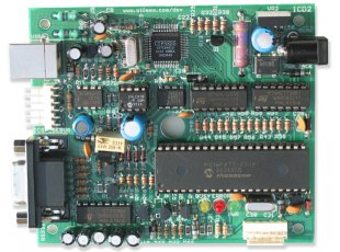
- Why are there two ICSP connectors on the PIC-ICD2, which one I should use?
- There is no functional difference between them and PIC-ICD2 is 100% compatible to MPLAB-ICD2. The only difference is the ICSP connector - Microchip uses a RJ45 phone jack connector, we use a 0.1" step connector
- Why are there two ICSP connectors on the PIC-ICD2, which one I should use?
- You should use the connector labelled ICSP-DEBUG next to USB connector, the other ICSP connector (down right on the picture) is the connector which we use to load PIC-ICD2 firmware and diagnostic the PIC-ICD2 during production tests.
- What should I know when connect PIC-ICD2 to target board?
- It's very important your target PIC MCLR not to be connected directly to the VCC! During the programming/debugging MCLR goes as high as 13VDC and if your target MCLR is connected directly to the target VCC you will blow either the PIC-ICD2 or your target board. Always use a 10K pullup resistor from MCLR to VCC.
- What should I know when connecting PIC-ICD2 and RS232 port?
- COM port should be set with HARDWARE FLOW CONTROL and FIFO buffers DISABLED.
- I'm on a very low budged. What is the difference between PIC-ICD2 and PIC-ICD2-TINY?
- There are two major differences between PIC-ICD2 and PIC-ICD2-TINY: 1. TINY only has a RS232 port and works slower than PIC-ICD2; 2. TINY has a fixed 13VDC Vpp while PIC-ICD2 has a variable voltage Vpp. Some new PIC microcontrollers have a max limit of 12.5V for Vpp and a diode drop circuit should be used if you work with TINY.